
Starting with the problem
There’s a quiet drag in production that people rarely name: monitors record a fault, controllers log nothing, and the testing tools report something else entirely. I’ve watched this pattern unfold during line audits and it has a predictable rhythm — long debugging sessions, shifting blame, and a slow erosion of trust in data. When you plan integration, start with the physical heart of the process: the transformer. A reliable resistance welding transformer is not decorative; it shapes signals, timing, and failure modes. The issue shows up most clearly at scale — think of assembly cells in Detroit automotive plants — where small mismatches cascade into production pauses and inspection headaches.
The core mismatch: signals versus expectations
Controllers expect clean, time-stamped events. Monitors expect proportional measurements they can analyze. Test tools expect reproducible inputs. Real-world wiring, cable lengths, and transformer saturations change those expectations into gray noise. This is a problem of translation: energy pulses get distorted by hardware, and firmware attempts to interpret those distortions without context. That mismatch is the root cause you must treat first, not last.
Hardware pairing and why the transformer matters
Choose hardware that speaks the same language. What works in a lab fails at duty cycle. Consider the transformer’s leakage inductance and secondary impedance because they shape current ramps and peak timing. If you’re pairing a modern controller with legacy weld heads, check that the controller’s sensing bandwidth aligns with the head and the transformer. For spot-specific work, a correctly specified spot welding transformer prevents misread pulses and keeps test readings meaningful.
Planning checklist: concrete steps before integration
– Map the signal chain: primary source → transformer → weld head → controller sensor → monitor input. – Measure nominal cable lengths and expected rise times on the floor rather than relying on datasheets. – Define acceptable timing windows and amplitude tolerance for every critical signal. – Standardize connectors and grounding to the same reference; floating grounds create phantom faults. – Reserve a validation slot on the line where you can run instrumented shots without interrupting production.
Testing strategy that prevents band-aid fixes
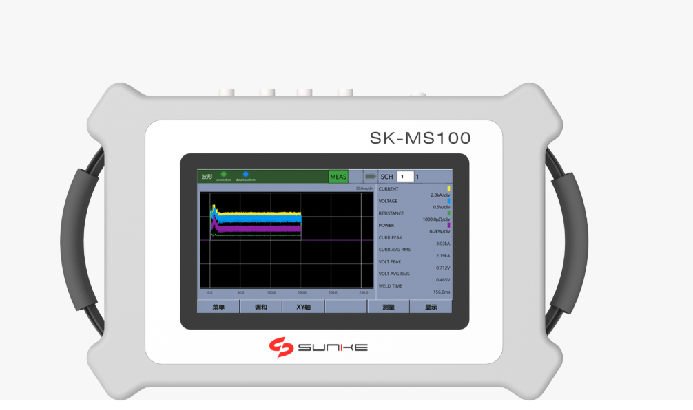
Run three controlled tests: bench, on-the-head, and in-line. Bench tests confirm electrical behavior with an oscilloscope and dummy loads. On-the-head tests confirm mechanical repeatability and contact resistance. In-line tests reveal cycle heating and duty-cycle effects. Log every test with the same sampling rates used by the monitor and controller. If your monitor’s sampling aliasing differs from the controller’s, reconcile it — do not patch it later with heuristics.
Common pitfalls and how to avoid them
– Overtrusting simulations: real transformers and contact resistances diverge from models. – Blind firmware updates: versions change timestamps and thresholds; validate after every update. – Ignoring thermal drift: transformers and electrodes shift values across shifts and seasons. – Mixing analogue and digital sensing without a clear calibration routine: you’ll get two truthful but incompatible stories.
Controller, monitor and data: alignment rules
Treat data alignment as a design objective. Decide which device is the source of truth for time and which for amplitude. If the monitor will be the authority for quality trending, feed it raw, unfiltered measurements and document any controller-side pre-processing. Implement a lightweight handshaking protocol: a start-of-shot marker, a primary energy marker, and an end-of-shot confirmation. Keep those markers consistent across firmware revisions.
Synthesis: plan that ends uncertainty
You can stop rotating blame and start fixing design. Begin by fixing the physical signal path — the transformer, cabling, and grounding — then align sampling and handshakes. Use the checklist above, test in three contexts, and codify who owns time and amplitude. The long view is simple: when equipment and data agree, troubleshooting becomes factual and fast; when they don’t, you spend weeks chasing ghosts. Practical solutions live where specification meets reality; that is where Sunke’s equipment and support fold into steady production, quietly turning ambiguous alarms into precise, useful signals.